
Turn article assumptions into a first actuator family, model class, and evidence request.
Open catalog RFQ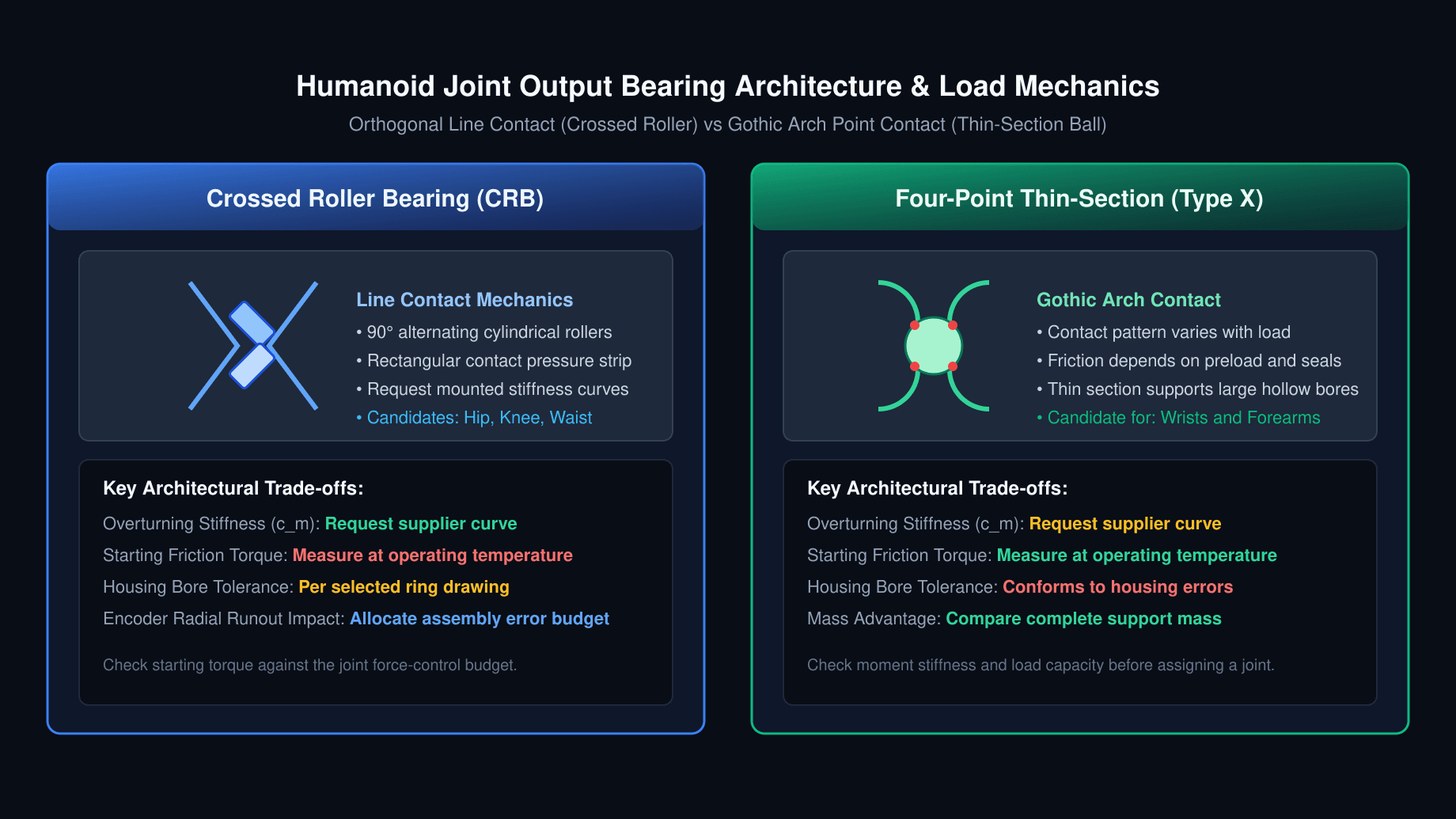
2026/11/11
Crossed Roller Bearings vs. Four-Point Contact Thin-Section Bearings in Humanoid Robot Actuators: Sourcing Moment Rigidity, Preload Classes, and Runout Tolerances
Compare crossed roller and four-point thin-section bearings for humanoid actuators. Review moment stiffness, preload, runout, and RFQ qualification checklist.
Quick answer: When comparing crossed roller bearings vs. four-point contact thin-section bearings for humanoid actuators, start with the output support's moment-deflection requirement. Crossed roller bearings are strong candidates for compact, heavily loaded hip, knee, waist, and shoulder supports. Four-point thin-section ball bearings are candidates where a large hollow bore and low support mass matter, including wrists and forearms. Neither topology guarantees a particular stiffness, starting torque, or runout simply from its name.
A four-point bearing can carry combined radial, axial, and moment loads, but the selected size, preload, supporting structure, and operating load determine whether it meets the joint requirement. Compare complete mounted assemblies rather than assuming a universal stiffness or mass advantage.
Three sourcing questions deserve explicit answers:
- Preload versus friction: Which manufacturer-defined clearance or preload condition is supplied, and what are the measured starting and running torque limits at the intended temperatures?
- Encoder accuracy: How much of the output encoder's error budget is allocated to bearing motion, hub eccentricity, scale mounting, and housing deformation? A free-bearing runout grade does not specify total assembled encoder error.
- Thermal retention: How does the steel ring remain located in an aluminum housing across the temperature range? The illustrative 100 mm interface below gains 69 µm of differential diametral clearance over a 60 K uniform temperature rise.
Use our Humanoid Robot Actuator Catalog to shortlist modules, or discuss support requirements for Highly Integrated Rotary Modules. Bring the load spectrum and error budget to that discussion rather than selecting a bearing by joint name alone.
Sourcing Scope, Method, and Verification Limits
Editorial review date: November 11, 2026.
Audience and region: Global mechatronics engineers, humanoid hardware architects, and procurement teams.
Scope: Structural output supports in rotary humanoid actuators with strain-wave, cycloidal, planetary, or direct-drive architectures. Motor-shaft high-speed bearings require a separate speed, lubrication, and rotor-support assessment.
Method: Engineering screening using the manufacturer reference entry points in Sources and References, qualitative architecture comparisons, and explicitly assumed numerical examples. No physical bearing tests, supplier inspection records, or customer outcomes are reported here. Example loads are not derived from a validated gait or a particular robot mass. Manufacturer product pages establish product context; they do not substantiate the assumed stiffness values, load factors, price ratios, or production acceptance limits.
Use limits: This guide helps prepare an RFQ and validation plan. Final selection requires the exact series drawing, manufacturer load calculation, thermal and mounting review, and representative assembly testing. Review again when the bearing series, housing, encoder, lubricant, or duty cycle changes.
Procurement Decision Matrix: Joint Bearing Topologies
These are candidate architectures, not approved part allocations. Bore and cross-section dimensions must follow the actual load spectrum and packaging study.
| Humanoid Joint Axis / Location | Mechanical Loading to Establish | Candidate Output Support | Packaging Question | Critical Sourcing Evidence | Relevant Product Pathway |
|---|---|---|---|---|---|
| Hip Roll & Hip Yaw | Cantilever moments and lateral shocks | Crossed roller ring | Is the complete support stiff enough within the bore envelope? | Mounted moment-deflection curve and shock calculation | High-Torque Leg Actuator Modules |
| Hip Pitch & Knee | Bending moments and foot-strike peaks | Crossed roller ring or independently justified alternative | Can the housing resist clamping and load deformation? | Static load check, preload definition, and hot torque test | Bipedal Leg Joint Actuators |
| Ankle Pitch & Ankle Roll | Ground reaction loads and multi-axis shock | Slim crossed roller or paired angular-contact support | How much axial space is available for the support span? | Combined-load assessment and oscillation test | Humanoid Linear Actuators & Linkages |
| Torso / Waist Yaw | Upper-body axial load and payload moments | Crossed roller ring, potentially with mounting holes | Is there space for fasteners and through-bore harnesses? | Bolt-joint analysis and loaded tilt measurement | Hollow-Shaft Joint Actuators |
| Shoulder Pitch & Abduction | Arm reach, payload moments, and shocks | Crossed roller or four-point thin-section bearing | What is the mass cost of the complete support? | Deflection and starting-torque comparison at matched loads | Compact Arm and Wrist Actuators |
| Elbow Flexion / Extension | Bending and repeated reversing motion | Four-point thin-section or crossed roller bearing | Does a single ring meet the tilt budget? | Reversal behavior, friction, and endurance test | Highly Integrated Rotary Modules |
| Wrist Pitch, Yaw & Roll | Tool moments and distal mass constraints | Four-point thin-section bearing or another qualified support | What hollow bore and cable clearance are needed? | Loaded runout, seal torque, and tool-tip deflection | Humanoid Arm and Hand Actuators |
1. Operating Physics: Line Contact vs. Point Contact
Crossed Roller Bearings: Orthogonal Line Contact
Crossed roller bearings arrange adjacent cylindrical rollers at right angles, allowing one compact ring to support loads in multiple directions. The nominal line contact spreads load over a different contact geometry from a ball's nominal point contact. Under real load, both contacts have finite areas and elastic deformation.
This geometry can support high moment rigidity in a short axial envelope. It does not establish a fixed stiffness multiplier relative to every ball bearing. Roller length, pitch diameter, raceway geometry, ring thickness, preload, and supporting structure all influence the mounted result. Ask for the slope of the moment-deflection curve around the intended operating point, not just a maximum moment rating.
Separators or cages manage rolling-element spacing and interaction. Full-complement and separated designs have different load, speed, friction, and lubrication trade-offs. Request the supplier's recommendation for the intended reversing motion instead of rejecting one construction universally.
Four-Point Contact Thin-Section Bearings: Gothic Arch Contact
A four-point thin-section ball bearing, such as the Kaydon Type X architecture, uses raceway geometry that permits radial, reversing axial, and moment support in one ring. The name describes potential contact locations; the actual loaded contact pattern depends on clearance, preload, and combined loading. The diagram below is a conceptual representation, not a loaded-contact simulation.
Thin sections are useful when a large bore must fit a restricted envelope. However, thin rings depend strongly on the shaft and housing for support. Ball contact does not automatically guarantee lower starting friction: seals, lubricant, preload, diameter, and temperature can dominate. Compare the actual candidates at the same installation and load conditions.
2. Electromechanical Comparison & Structural Diagram
The schematic identifies the contact architectures and the evidence to request. It is an editorial illustration, not a photograph, dimensional drawing, or measured performance comparison.
3. Tilting Moment Rigidity & Cantilever Deflection Analysis
For a force perpendicular to a lever arm, the moment is M = F × L. For general loading, use the vector cross product and include all simultaneous forces. Keep output-axis drive torque separate from overturning moment; they act about different axes and cannot be exchanged in a bearing calculation.
If a local linear approximation is appropriate, tilt is θ = M / c_m, where moment stiffness c_m is in N·m/rad. A point at distance L from the support moves approximately Δx = θ × L for small angles. These equations describe bearing contribution only; housing, reducer, link, and fastener compliance can add to the displacement.
Worked Comparison: Hypothetical Hip Roll Support
Assume an overturning moment of 180 N·m and a distance of 0.85 m from bearing center to foot. Two hypothetical supports have assumed local stiffnesses of 320 kN·m/rad and 65 kN·m/rad. These are sensitivity-analysis inputs, not measured values or specifications for any THK, IKO, or Kaydon part. No geometrically interchangeable parts are asserted.
Support A:
θ = 180 / 320,000 = 0.0005625 rad = 1.93 arcmin
Δx = 0.0005625 × 0.85 = 0.000478 m = 0.478 mm

Support B:
θ = 180 / 65,000 = 0.002769 rad = 9.52 arcmin
Δx = 0.002769 × 0.85 = 0.002354 m = 2.354 mm
The assumed stiffness ratio produces approximately 4.9 times the displacement in Support B. It demonstrates why a procurement specification needs a mounted deflection limit. It does not prove that all crossed roller bearings outperform all four-point bearings by this ratio, or predict gait instability.
A more useful requirement runs in reverse: if the allowed support contribution is 0.5 mm under this load, the minimum local stiffness is c_m = M × L / Δx = 306,000 N·m/rad, or 306 kN·m/rad. Allocate the rest of the joint's deflection budget separately and confirm the requirement across the actual load range.
4. Preload Classes, Breakaway Friction Torque, and Thermal Limits
Preload creates internal contact load before an external working load is applied. It can remove free clearance and increase stiffness, while also changing friction, heat generation, and load distribution. Internal bearing preload and housing interference fit are different quantities: a mounting fit can change the installed clearance but is not a substitute for a defined internal preload specification.
Preload Codes Are Manufacturer-Specific
Do not equate codes such as C0, C1, C2, V1, or T0 across brands and series. A code may designate a clearance condition in one family and something different in another. Even a label such as “light preload” requires a numerical definition and measurement method.
| Quoted Condition | Information to Request | Engineering Check | Procurement Acceptance Basis |
|---|---|---|---|
| Positive internal clearance | Actual range, direction, and measurement load | Reversal motion and loaded tilt | Agreed maximum play after mounting |
| Nominal zero clearance | Tolerance band around zero | Fit and temperature can change the condition | Mounted torque and deflection limits |
| Light preload | Vendor code plus clearance or preload-force range | Stiffness versus friction budget | Specified start/run torque test |
| Higher preload | Exact value and justification | Heat, contact loading, and low-speed motion | Qualified operating envelope, not a blanket prohibition |
Starting Torque and Frictional Heat
Starting torque is the torque required to initiate motion under defined conditions. Running torque must be measured separately at the intended speed, load, lubrication, and temperature. Friction can mask small external disturbances in motor-current-based torque estimates; a dedicated output torque sensor has a different sensing boundary and should be assessed accordingly.
Frictional power is P_loss = T_friction × ω. As an illustrative operating point, 1 N·m of running friction at 45 rpm gives ω = 2π × 45 / 60 = 4.71 rad/s and 4.71 W. Starting torque alone cannot establish continuous heating. For reversing motion, integrate frictional work over the measured speed and load history.
Do not multiply output-support friction by the gearbox ratio when reporting its contribution at the joint output. Motor-side friction and reducer losses require their own transmission model. Select preload using the stiffness target, available thermal path, and acceptable starting torque, then verify an assembled cold-to-hot sweep.
For an integrated module comparison, send this torque and temperature envelope with your inquiry for Highly Integrated Rotary Modules.
5. Bearing Runout and Off-Axis Rotary Encoder Accuracy
Some actuator architectures use separate motor-side and output-side encoders; see Dual Absolute Encoders vs Single-Encoder Joint Modules. For an output encoder mounted on the bearing-supported hub, bearing motion is one contributor to scale eccentricity and air-gap variation. Hub machining, mounting datums, scale installation, and deformation under load also matter.
Distinguish Eccentricity from Total Indicated Runout
For an ideal single-readhead circular scale with small eccentricity e relative to track radius R, a first-order geometric error estimate is θ_error,peak ≈ e / R in radians. This screens the eccentricity contribution; it does not model every magnetic sensor's air-gap response or compensation algorithm.
Eccentricity is an amplitude. For a perfectly round track displaced from the rotation axis, radial total indicated runout (TIR) is 2e. A real TIR measurement can also include roundness, tilt, and probe effects, so dividing it by two requires that eccentricity dominates. Specify the datum, measurement location, load, and temperature with every runout requirement.
Numerical Example: A 70 mm Diameter Track
Assume R = 35 mm and ideal eccentricity-dominated motion:
Case A: e = 15 µm (30 µm radial TIR for an ideal circular track)
θ_error,peak ≈ 0.015 / 35 = 0.0004286 rad = 88.4 arcsec

Case B: e = 3 µm (6 µm radial TIR for an ideal circular track)
θ_error,peak ≈ 0.003 / 35 = 0.0000857 rad = 17.7 arcsec
These are hypothetical geometric error amplitudes, not precision-grade guarantees. If the bearing is quoted at P4 or another accuracy class, obtain the actual numerical tolerance for the exact size and measured feature. A grade alone does not establish mounted encoder performance.
A once-per-revolution position error creates a velocity-error component at the mechanical rotation frequency when differentiated. Its effect on the control loop depends on speed, filtering, estimator design, and encoder compensation; no fixed bandwidth loss follows from the runout number. Repeat encoder checks under representative radial, axial, and overturning loads. A calibration table can remove repeatable error but cannot guarantee compensation for changing thermal or load-dependent deformation.
6. Housing Machining Tolerances & Bimetallic Thermal Expansion
Slender bearing rings can deform with their mounting surfaces. Integrated mounting holes simplify retention, but they do not isolate a raceway from housing distortion or uneven bolt loading. Machine and inspect the complete support interfaces using the selected manufacturer's installation requirements.
Drawing and Inspection Checklist
The following are specification fields, not universal ISO limits. For example, an H7 bore designation controls a size tolerance zone; it does not independently specify roundness, assembled clearance, or whether a mating fit is an interference fit.
| Dimension / Feature | Drawing Requirement to Define | Verification Method | Failure Mode to Investigate |
|---|---|---|---|
| Housing bore diameter | Size zone and resulting fit for the exact ring | Measure bore and ring over the temperature range | Ring creep or excessive mounted preload |
| Shaft pilot diameter | Fit, cylindricity, and datum relation | Multiple axial and angular measurements | Ring slippage or local distortion |
| Clamping face | Flatness and perpendicularity to the pilot datum | Surface inspection before and after assembly | Tilted support and uneven contact loading |
| Mounting fasteners | Size, grade, engagement, tightening sequence, and torque | Controlled assembly with final rotation check | Raceway distortion or joint separation |
| Surface texture | Roughness and finishing method on each locating face | Profile measurement where required | Seating instability or loss of retention |
| Shoulder and relief | Chamfer and corner radius compatible with ring drawing | Check clearance and full face seating | Ring held off the shoulder by a corner |
| Housing stiffness | Wall and flange design under working loads | Analysis correlated with loaded assembly tests | Acceptable free-ring data but excessive installed tilt |
Illustrative Steel–Aluminum Thermal Calculation
Assume a steel ring and aluminum bore both start at 100 mm and 20°C and reach a uniform 80°C. Use assumed expansion coefficients of 11.7 × 10⁻⁶/K for steel and 23.2 × 10⁻⁶/K for aluminum. Exact alloy data, temperature gradients, and mechanical constraints must replace these assumptions in a release calculation.
Temperature rise ΔT = 60 K
Differential coefficient Δα = (23.2 − 11.7) × 10⁻⁶/K
Differential diameter growth = D × Δα × ΔT
                            = 100 × 11.5 × 10⁻⁶ × 60
                            = 0.069 mm = 69 µm

Aluminum bore growth alone = 139.2 µm
Steel ring growth alone    = 70.2 µm
The 69 µm is the increase in diametral clearance between freely expanding components, not the aluminum bore's absolute growth. In this simplified model, an initial 20 µm diametral interference would become approximately 49 µm clearance. A real clamped assembly needs a constrained thermal model; axial clamp force may increase or decrease depending on the stack and temperature distribution.
Possible countermeasures include a compatible liner, a revised fit, positive retention, or a bolted bearing interface. Each needs verification. No sleeve material or mounting-hole pattern automatically eliminates thermal preload changes. Inspect starting torque, loaded tilt, and ring retention at both temperature extremes.
7. Engineering Specification & Sourcing Comparison Matrix
Use this qualitative matrix to organize supplier evidence. It intentionally avoids universal stiffness, mass, runout, and price multipliers: those require matched part numbers, mounting conditions, and comparable quotations.
| Specification Parameter | Crossed Roller Ring | Crossed Roller Ring with Mounting Holes | Four-Point Thin-Section Ball Bearing | Paired Angular-Contact Ball Support |
|---|---|---|---|---|
| Contact architecture | Alternating roller orientations | Alternating roller orientations | Gothic arch raceways | Opposed directional ball contacts |
| Moment support | In one compact ring | In one compact ring | Possible within the selected load and tilt limits | Depends strongly on arrangement and support span |
| Moment stiffness evidence | Mounted moment-deflection curve | Curve including bolt and flange conditions | Curve at specified clearance and load | Curve for the complete matched assembly |
| Axial loading | Bidirectional within catalog limits | Bidirectional within catalog limits | Bidirectional within catalog limits | Bidirectional when the pair is arranged appropriately |
| Starting friction | Measure with specified preload and seals | Measure after final bolt tightening | Measure; point contact alone does not guarantee low friction | Include both bearings, seals, and preload system |
| Mass comparison | Include clamps and housing | Include bolts and supporting flange | Include required housing reinforcement | Include second bearing, spacer, and retention |
| Housing sensitivity | Ring support and clamping matter | Mounting holes do not remove distortion risk | Thin rings need adequate support | Alignment and seat spacing matter |
| Runout specification | Numerical limit for exact feature and size | Include mounted condition | Numerical limit plus datum definition | Define assembly runout and preload state |
| Oscillating duty | Validate lubrication and reversal behavior | Validate lubrication and fastener retention | Validate lubrication and reversal behavior | Validate both contact sets under reversing motion |
| Preload procurement | Series-specific code and range | Series-specific code and mounted torque | Clearance or preload definition from vendor | Matching method and installed preload |
| Commercial comparison | Quote same volume and inspection scope | Include assembly and machining costs | Include housing and inspection costs | Include matching, spacers, and assembly labor |
8. Sizing Walkthrough: Overturning Moment & Bearing Fatigue Life
This is an arithmetic screening example, not validation of a named bearing or robot. A fatigue calculation cannot by itself qualify impact survival, small-angle oscillation, or assembled positioning performance.
Step 1: Define an Illustrative Operating Point
Assume radial force 450 N, axial force 850 N, overturning moment 140 N·m, and equivalent continuous rotation at 45 rpm. These simultaneous loads and speed are chosen inputs, not a measured knee duty cycle. Actual joint data must include time histories, load directions, reversals, dwell periods, shock peaks, and temperatures.
Step 2: Define Hypothetical Rating Inputs
Assume a roller-bearing dynamic rating C = 21,200 N, static rating C₀ = 28,400 N, and rolling-element pitch diameter d_p = 85 mm. These are hypothetical inputs and are not ratings for THK RB7013 or another commercial part. Obtain the actual pitch diameter from the supplier; (bore + outside diameter) / 2 is only a geometric estimate.
For the life arithmetic below, assume that C uses a one-million-revolution rating basis. Some catalogs use different rating conventions or reference lives. Confirm and convert the basis before combining a supplier's rating with a life equation.
Step 3: Illustrate an Equivalent-Load Calculation
Use the assumed screening relation P = X × (F_r + 2M / d_p) + Y × F_a, with assumed factors X = 1 and Y = 0.45. This relation and these coefficients are not asserted to be a universal ISO 281 or THK combined-load rule. The selected manufacturer's contact geometry, factor definitions, load directions, and moment treatment must determine the approved calculation.
Moment in consistent units: M = 140,000 N·mm
Assumed moment-equivalent term = 2 × 140,000 / 85 = 3,294.1 N
P = 450 + 3,294.1 + 0.45 × 850 = 4,126.6 N
Do not reuse these factors for a four-point ball bearing or angular-contact pair. Ask the manufacturer to return its calculation sheet with all source tables and factors identified.
Step 4: Reproduce the Fatigue Arithmetic
For a roller-bearing example with the stated rating basis, use exponent p = 10/3. For many ball-bearing basic rating calculations the exponent is 3; other assumptions still require checking.
L10 = (C / P)^(10/3), in millions of revolutions
    = (21,200 / 4,126.617647)^(10/3)
    ≈ 233.96 million revolutions

L10h = 1,000,000 × L10 / (60 × n)
     ≈ 1,000,000 × 233.9585 / (60 × 45)
     ≈ 86,651 hours
Basic L10 denotes a statistical fatigue rating life associated with 90% survival under its defined conditions; it is not a guaranteed service life for every bearing. The large illustrative hour result cannot predict grease life, wear, false brinelling, contamination effects, or shock damage. Reversing joints require an appropriate motion and load-spectrum model rather than blindly inserting average joint speed into a continuous-rotation equation.
Step 5: Screen a Hypothetical Static Peak
For a second assumed event, use M_max = 320 N·m, F_a,max = 1,800 N, and F_r = 450 N. With assumed factors X₀ = 1 and Y₀ = 0.44:
P0 = 450 + 2 × 320,000 / 85 + 0.44 × 1,800
   = 8,771.4 N
Static safety factor fs = C0 / P0 = 28,400 / 8,771.4 ≈ 3.24
The factor 3.24 is an arithmetic result, not a pass threshold or evidence that a joint will survive a stumble. Obtain the vendor's static-equivalent-load method and recommended safety factor for the actual shock environment. Check ring strength, bolts, mounting faces, and loaded deflection separately before any design release.
9. 10-Point RFQ Procurement Checklist for Humanoid Joint Bearings
Send the same evidence request to every candidate supplier so procurement can compare equivalent deliverables:
- Moment-deflection curve: Request test loads, mounting stiffness, preload, temperature, and measurement location. Distinguish catalog moment capacity from allowable deflection.
- Runout inspection: Define radial and axial features, datums, load state, and whether the limit is TIR or an eccentricity amplitude. Allocate the encoder assembly budget before choosing a grade.
- Internal preload: Require the exact series code, numerical range, and measurement method, plus starting and running torque limits before and after installation.
- Rolling-element construction: Identify separators, cage, or full-complement construction and request evidence for the intended reversing angle, speed, and duty cycle.
- Lubrication: Specify oscillation amplitude, dwell, transport vibration, temperature, and service interval. Ask for grease compatibility and an application-based fretting assessment rather than mandating one grease chemistry.
- Materials and traceability: Confirm ring and rolling-element materials, heat treatment, corrosion needs, and available material/lot records. Do not assume all products use one bearing-steel grade.
- Mounting requirements: Obtain the vendor's fit, geometric tolerances, supporting wall/flange requirements, fastener details, and installation procedure for the exact size.
- Architecture options: Ask whether mounting holes, separate clamps, or a paired support best meet the bore, stiffness, and assembly-cost requirements; compare complete support mass.
- Temperature and seals: Request validated seal/grease temperature ranges, cold-start torque, hot running torque, and thermal retention behavior for the actual joint envelope.
- Sample-to-production acceptance: Agree sample quantities, inspection coverage, report format, lot or individual traceability, acceptance limits, and the change-notification process before ordering.
10. Frequently Asked Questions (FAQ)
Can deep groove ball bearings support a humanoid joint?
Yes, when the complete arrangement meets the load and deflection requirements. A suitably spaced pair can resist overturning moment. A crossed roller or four-point support can offer a shorter package, but there is no universal minimum spacing or mass penalty for a deep-groove arrangement.
When should we choose four-point thin-section bearings?
Shortlist them when a large bore, restricted section, and support mass are important. Then check loaded tilt, static capacity, oscillation behavior, and starting torque. Wrist and forearm applications can be suitable, but joint location is not an approval criterion and no universal 15 N·m cutoff applies.
Does bearing preload protect a strain-wave reducer?
Output support alignment matters to the reducer interface. However, raising preload can change friction, heat, and ring distortion. Follow the reducer's mounting and permissible external-load requirements; a generic “light preload” code does not guarantee improved gear life.
Can we mount a steel ring in a bare aluminum housing?
Possibly, provided the fit and retention are qualified across the temperature range. Differential expansion can relax interference, while clamping and thermal gradients can alter the loaded condition. A liner or bolted ring is one design option, not an automatic solution.
What causes false brinelling in an actuator bearing?
Small repeated relative motion or transport vibration can damage contacts when lubrication is inadequate for the motion. Risk depends on load, amplitude, lubricant, and time. Ask the bearing supplier for an oscillation-specific lubrication and validation plan; a calculated rolling-fatigue life does not screen this failure mode.
Does radial runout always create high-frequency velocity ripple?
No. Ideal eccentricity produces a once-per-revolution error component. Its frequency follows mechanical speed; other scale and sensor errors may have different harmonics. Evaluate the encoder assembly and control estimator together rather than inferring a fixed control bandwidth from a bearing grade.
Are ceramic balls worthwhile for low-speed joint supports?
Only with a defined requirement and a qualified supplier proposal. Lower rolling-element mass may matter little at low output speed, and electrical insulation must be assessed within the full current path. Do not assume a universal price multiplier, stiffness improvement, or complete protection against bearing-current damage.
Are bearing accuracy grades interchangeable across suppliers?
Do not assume so. Require the applicable standard or proprietary definition, size-dependent numerical limits, measurement datum, and mounted inspection procedure. A P4 designation alone does not promise 3 µm encoder runout or a specified friction torque.
Can an encoder lookup table replace precision mounting?
Calibration can reduce repeatable position error under its calibration conditions. It cannot guarantee correction of changing load-dependent tilt, temperature drift, or nonrepeatable bearing motion. Keep mechanical error limits and loaded encoder verification in the acceptance plan.
How does a hollow shaft change the bearing decision?
It establishes a minimum clear bore for cables, tubing, and installation tools. Check minimum bend radii and moving-harness clearances as well as bearing dimensions. Both crossed roller and thin-section ball architectures can support hollow-shaft designs; compare the complete housing and retention envelope.
11. Sources and References
Reference review date: November 11, 2026. These official manufacturer resources provide product context and routes to current engineering documentation. They are not evidence of physical tests performed by this publisher or of the illustrative numerical inputs above.
- THK — Official English manufacturer portal: Starting point for requesting current Cross-Roller Ring documentation and exact series drawings. The earlier legacy catalog link now redirects to this portal; it must not be treated as a verified copy of Catalog 382 or as support for a particular rating.
- Kaydon Bearings — Engineering: Engineering entry point linked in Kaydon's own site navigation, replacing the obsolete Reali-Slim URL. Obtain the current thin-section catalog and part-specific contact, clearance, fit, and load data through the manufacturer. Use the engineering entry point to obtain current documentation; model-specific limits require the applicable drawing and catalog revision.
- Harmonic Drive — Rotary Actuators: Confirms an integrated actuator product context combining motors, gearing, cross roller bearings, drives, and encoders, including hollow-shaft architectures. The product overview does not provide the example load factors or establish bearing stiffness for a specific module.
Before releasing a purchase order, retain the supplier's drawing revision, rating convention, calculation sheet, and inspection agreement with the RFQ. Product-family names and an accessible corporate page are not substitutes for this evidence.
12. Next Steps: Streamline Your Actuator Sourcing
When configuring structural bearings for your humanoid robot program, never evaluate bearing ratings in isolation from your joint load spectrum, encoder architecture, and housing machining limits.
To expedite sample testing and production validation:
- Explore Modular Joint Assemblies: Review candidate rotary joint modules and request the bearing configuration in the Humanoid Robot Actuator Catalog.
- Lower-Limb High-Moment Solutions: Evaluate High-Torque Leg Actuator Modules and Bipedal Leg Joint Actuators and request evidence against your specified impact and overturning-moment loads.
- Distal Limb & Arm Modules: Compare ultra-lightweight joint options in Compact Arm and Wrist Actuators and Humanoid Arm and Hand Actuators.
- Hollow-Shaft Cabling Architectures: Check envelope dimensions and harness clearances in Hollow-Shaft Joint Actuators.
- Custom OEM Integration & BOM Optimization: Submit your joint mechanical envelope, target moment loads, and encoder specifications through Actuator BOM Integration to request a bearing/reducer interface review and identify which drawings and validation records are available.
Author

Categories
Buyer path
After Reading
Use the guide to choose the next sourcing action.
Convert the guide into application-risk notes before asking for samples or controlled files.
Send prototype contextCarry accepted article checklists into sample release, pilot supply, and OEM documentation control.
Prepare OEM sample planSourcing Scope, Method, and Verification LimitsProcurement Decision Matrix: Joint Bearing Topologies1. Operating Physics: Line Contact vs. Point ContactCrossed Roller Bearings: Orthogonal Line ContactFour-Point Contact Thin-Section Bearings: Gothic Arch Contact2. Electromechanical Comparison & Structural Diagram3. Tilting Moment Rigidity & Cantilever Deflection AnalysisWorked Comparison: Hypothetical Hip Roll Support4. Preload Classes, Breakaway Friction Torque, and Thermal LimitsPreload Codes Are Manufacturer-SpecificStarting Torque and Frictional Heat5. Bearing Runout and Off-Axis Rotary Encoder AccuracyDistinguish Eccentricity from Total Indicated RunoutNumerical Example: A 70 mm Diameter Track6. Housing Machining Tolerances & Bimetallic Thermal ExpansionDrawing and Inspection ChecklistIllustrative Steel–Aluminum Thermal Calculation7. Engineering Specification & Sourcing Comparison Matrix8. Sizing Walkthrough: Overturning Moment & Bearing Fatigue LifeStep 1: Define an Illustrative Operating PointStep 2: Define Hypothetical Rating InputsStep 3: Illustrate an Equivalent-Load CalculationStep 4: Reproduce the Fatigue ArithmeticStep 5: Screen a Hypothetical Static Peak9. 10-Point RFQ Procurement Checklist for Humanoid Joint Bearings10. Frequently Asked Questions (FAQ)Can deep groove ball bearings support a humanoid joint?When should we choose four-point thin-section bearings?Does bearing preload protect a strain-wave reducer?Can we mount a steel ring in a bare aluminum housing?What causes false brinelling in an actuator bearing?Does radial runout always create high-frequency velocity ripple?Are ceramic balls worthwhile for low-speed joint supports?Are bearing accuracy grades interchangeable across suppliers?Can an encoder lookup table replace precision mounting?How does a hollow shaft change the bearing decision?11. Sources and References12. Next Steps: Streamline Your Actuator Sourcing
More Posts
Engineering NotesProcurement Guides
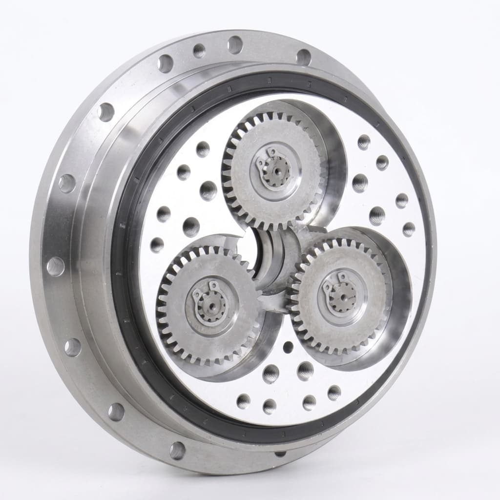
Strain Wave vs. Cycloidal Reducers for Humanoid Rotary Actuators: A 2026 Sourcing & Engineering Guide
Compare strain wave vs. cycloidal reducers for humanoid rotary actuators. Check shock ratings, lost motion, sizing examples, and prepare your supplier RFQ.
Engineering NotesProcurement Guides
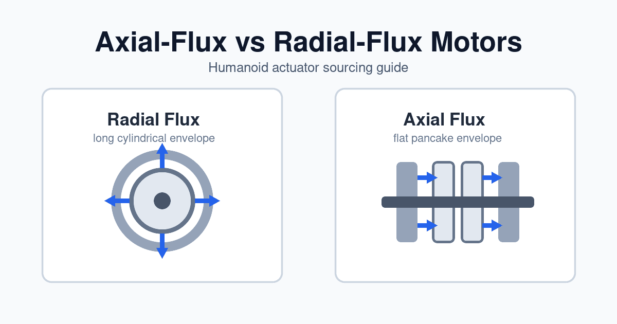
Axial-Flux vs. Radial-Flux Motors for Humanoid Actuators: A 2026 Sourcing Guide
Compare axial-flux vs radial-flux motors for humanoid actuators in 2026: torque density, thermal limits, tooling cost, joint fit, and RFQ sourcing checks.

Engineering NotesProcurement Guides
Dual Absolute Encoders vs. Single-Encoder Joint Modules for Humanoids: Sourcing, Deflection Sensing, and Functional Safety
Compare dual absolute encoders vs single-encoder humanoid joints. Assess deflection, startup position, safety evidence and BOM trade-offs with an RFQ checklist.