
Turn article assumptions into a first actuator family, model class, and evidence request.
Open catalog RFQ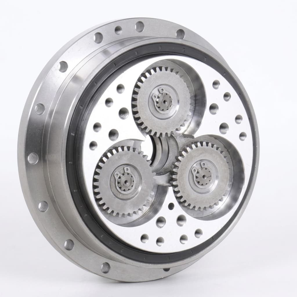
2026/10/29
Strain Wave vs. Cycloidal Reducers for Humanoid Rotary Actuators: A 2026 Sourcing & Engineering Guide
Compare strain wave vs. cycloidal reducers for humanoid rotary actuators. Check shock ratings, lost motion, sizing examples, and prepare your supplier RFQ.
Quick answer: In a strain wave vs. cycloidal reducer comparison for humanoid rotary actuators, start with strain wave candidates when joint mass, compact packaging, and low backlash dominate. Start with precision cycloidal candidates when output stiffness, bearing moments, and documented overload capability dominate. Joint location alone does not decide the winner: either family needs model-specific torque, speed, thermal, and lifetime checks. Low-ratio planetary or quasi-direct-drive (QDD) architectures also belong on the shortlist when impact response and backdrivability matter more than high reduction.
Published and reviewed: October 29, 2026. Scope: Global engineering and procurement guidance for electromechanical humanoid robot rotary actuator modules. This is a source-based comparison with an editorial selection framework and explicitly illustrative calculations. We have not conducted a comparative hardware endurance test or collected current supplier quotations. Manufacturer specifications apply to their named series, not every reducer of the same topology. Validate your joint trajectory, cooling, bearing loads, and abnormal-event limits before design freeze.
For hardware engineering leads and procurement teams, the useful decision is whether a candidate meets the same joint duty and acceptance tests as its alternatives. The comparison table, joint allocation matrix, sizing example, and 10-point RFQ checklist below provide a common evaluation method.
To compare complete modules alongside reducer components, review our Highly Integrated Rotary Modules, High-Torque Leg Actuator Modules, and Compact Arm and Wrist Actuators. These are sourcing categories; confirm the actual gearbox model and test evidence in the quotation.
1. The Rotary Joint Bottleneck in Humanoids
A humanoid carries its actuators with it. Moving mass farther from a joint increases limb inertia; a compact reducer can therefore help packaging without automatically improving force control or efficiency. Ground contact adds another constraint: output torque depends on posture, contact force, lever arm, compliance, and the duration of an impact. Body acceleration in g is not interchangeable with a gearbox torque overload factor.
Use three separate load cases when comparing reducers:
- Repeated movement: Record signed torque and output speed over the full walking, lifting, or manipulation cycle.
- Starts, reversals, and recovery: Check allowed repeated peak torque, duration, frequency, bearing loads, and controller behavior.
- Abnormal events: Define emergency stops and falls separately, including whether inspection or replacement is required afterward.
A family-level claim such as “five times rated torque” cannot replace this load spectrum. The recommendation throughout this guide is to shortlist by constraints, then qualify the exact module.
2. Operating Mechanics: Elastic Deformation vs. Rolling Pin Contact
2.1 Strain Wave (Harmonic Drive) Mechanics
A strain wave gear combines an elliptical wave generator, an elastic toothed flexspline, and a rigid circular spline. The wave generator creates two engagement regions. With the circular spline fixed and two more teeth than the flexspline, the output moves backward by two teeth per input revolution. Harmonic Drive's operating-principle explanation describes this arrangement and its zero-backlash characteristic.
The reduction magnitude is R = Z_fs / (Z_cs - Z_fs). For an illustrative 200-tooth flexspline and 202-tooth circular spline, R = 100; the output rotates opposite the input in this configuration. Changing the fixed member changes the kinematics. Zero backlash does not mean zero loaded angular deflection.

Application illustration; this image does not show reducer internals or a tested actuator configuration.
2.2 Precision Cycloidal (RV) Mechanics
Cycloidal reducers use eccentric motion and multiple disc-to-pin contacts. In a simplified single cycloidal stage with a stationary ring of N pins and a disc with N - 1 lobes, the reduction magnitude is R = N - 1. This is a kinematic illustration, not the full ratio equation for an RV assembly: a preceding spur stage and the chosen input/output arrangement must also be included.
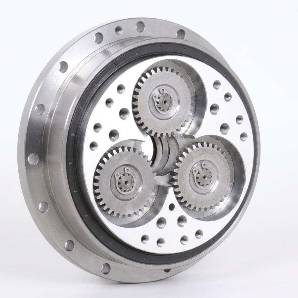
Product illustration. Ratings must come from the identified model's datasheet; the image itself establishes no torque or impact rating.
The number of contacts carrying substantial load depends on geometry, tolerances, deformation, and operating load. Do not assume a fixed percentage of pins shares every impact equally.
3. Contact Mechanics and Shock Load Survivability
The diagram contrasts engagement arrangements. It is a schematic, not a stress simulation, a pin-count specification, or proof that one family survives a robot fall.
3.1 Ratcheting and Overload Limits in Strain Wave Gears
Severe overload can lead to tooth skipping or damage in a strain wave gear. Obtain the selected model's repeated-peak and momentary limits, and ask whether the manufacturer publishes a ratcheting threshold. Treat any such threshold as a failure boundary, not an allowable operating torque. There is no universal ratcheting-to-rated-torque ratio established by the sources below.
Normal flexspline deformation is part of the design, not evidence of imminent failure. Harmonic Drive's technology note states that flexspline stresses remain below the material endurance limit when used within catalog ratings. That statement does not establish the service life of bearings, lubrication, or a complete humanoid joint.
3.2 What a Cycloidal Emergency Rating Actually Covers
Nabtesco's RV-N specifications distinguish rated, acceleration/deceleration, and emergency-stop torque. For the RV-25N, the published values are 245 N·m rated, 612 N·m acceleration/deceleration, and 1,225 N·m emergency stop. Its listed mass is 3.8 kg. This is a concrete example of why torque margin and carried mass must be evaluated together.
The emergency figure is five times rated torque; it is not a continuous or repeated heel-strike rating. Obtain the permitted duration, occurrence count, output speed, and post-event inspection requirements. Pins, discs, bearings, shafts, and housings can still suffer overload damage. A reducer rating alone does not qualify the robot's structure or fall behavior.
4. Torsional Stiffness and Lost Motion Over Operating Life
4.1 Backlash, Lost Motion, and Loaded Deflection Are Different
Backlash describes clearance on reversal; lost motion measurements also capture low-load torsional behavior under a specified test method. Loaded deflection additionally depends on stiffness, bearings, housing, and interfaces. Ask for the full torque-angle hysteresis curve rather than comparing an isolated “zero backlash” label with another supplier's lost-motion value.
The peer-reviewed study Hrcek et al., Materials 14(17), 5057 (2021) analyzes two harmonic-drive geometries using a lost-motion loading level of 4% of rated output torque, with the wave generator locked and circular spline fixed. This illustrates why amplitude and fixture conditions must accompany the number; it does not establish a universal test protocol or a humanoid endurance result.
For controller modeling, request stiffness segments and their actual torque boundaries. If the catalog supplies K1, K2, and K3, use its definitions; do not impose universal 20% and 50% transition points. Likewise, do not assume every cycloidal reducer has a perfectly linear curve or a fixed stiffness advantage at equal mass.
4.2 A Practical Endurance Acceptance Method
Neither zero initial backlash nor a low initial lost-motion figure predicts fleet lifetime. Agree a test before ordering pilot samples:
- Record baseline lost motion, starting torque, loaded stiffness, and transmission error at a defined temperature and lubrication condition.
- Apply a representative oscillation and load spectrum, recording reversals, input revolutions, torque peaks, speed, dwell, and temperature.
- Repeat the same measurements at agreed cycle intervals and after specified abnormal events.
- Set absolute limits and allowed change from baseline using the robot's tracking and balance requirements.
Report cycles and input revolutions alongside hours. Flexspline bending follows wave-generator rotation; gait cadence alone cannot be converted into flexspline fatigue cycles. The cited sources provide no general “failure after 2,500 hours” or “less than 20% degradation after 10,000 hours” rule for humanoids.
5. Engineering & Sourcing Comparison
This table is a screening framework. Unless a named series is stated, entries are evaluation questions rather than guaranteed family-wide performance.
| Selection parameter | Strain wave candidate | Precision cycloidal candidate | Engineering & procurement gate |
|---|---|---|---|
| Transmission principle | Elastic flexspline and toothed engagement | Eccentric disc and multiple pin contacts | Identify the actual mechanism and complete assembly. |
| Reduction ratio | Check available ratio and input configuration | Include any preceding spur stage | Match output speed and allowable input speed. |
| Backlash / lost motion | Zero backlash can coexist with elastic deflection | Request the model's hysteresis data | Compare equal test amplitude, temperature, and fixtures. |
| Repeated peak torque | Require model- and ratio-specific limits | Require model-specific acceleration/deceleration limits | Check duration and occurrence frequency. |
| Emergency torque | Do not use ratcheting as an operating limit | RV-N provides a separate emergency-stop rating | Keep abnormal events separate from repeated gait duty. |
| Stiffness | Use the supplied nonlinear torque-angle curve | Use measured or catalog curves for the selected model | Include bearing, housing, and interface compliance. |
| Mass and envelope | Compact configurations can suit constrained joints | Check torque capability against carried mass | Compare full modules, including required bearings. |
| Output bearing | May be integrated or separately specified | May be integrated or separately specified | Check radial, axial, and tilting loads together. |
| Drag / backdrivability | Measure starting and reverse-drive torque | Measure starting and reverse-drive torque | Test at relevant speed and cold/warm temperatures. |
| Lubrication / temperature | Follow the specified lubricant and fill procedure | Follow the specified lubricant and fill procedure | Confirm mounting, cooling, seals, and service interval. |
| Endurance evidence | Require representative duty-test records | Require representative duty-test records | Compare common acceptance limits and cycle counts. |
| Price and lead time | Obtain a dated, configured quotation | Obtain a dated, configured quotation | Include bearings, inspection, freight, and NRE. |
Worked Sizing Example: Separate Running Duty from an Impact
Illustrative inputs, not measured robot data: Suppose one output joint operates at 20 N·m for 40% of a cycle, 80 N·m for 50%, and 0 N·m for 10%. A separate abnormal-event requirement is 300 N·m for 20 milliseconds.
The output torque RMS is sqrt(20² × 0.40 + 80² × 0.50 + 0² × 0.10) = 58.0 N·m. This is a preliminary motor copper-loss indicator under simplified assumptions. It is not the reducer manufacturer's equivalent-load or bearing-life calculation. Gearbox selection still requires the torque-speed-time trace, the supplier's load-life method, and a thermal model. Include ordinary motion peaks even when the RMS is low.
For an illustrative motor rotor inertia of 0.00002 kg·m², a 100:1 ratio reflects J_output = J_motor × R² = 0.20 kg·m² to the output. At 50:1 it is 0.05 kg·m², before gearbox inertia. Thus, reducer family alone cannot establish impact transparency or backdrivability.
The 300 N·m event requires its own duration and occurrence check. Even if a catalog emergency limit exceeds it, that does not approve repeated 300 N·m operation or qualify the output bearing moment. A candidate advances only when every relevant limit has evidence.
Use the table to assemble a shortlist of integrated rotary modules, then request the same torque-speed and acceptance-test packet for each candidate.
6. Joint-by-Joint Architectural Allocation Matrix
These are starting points for comparison, not prescriptions or published torque ranges. Joint names and robot mass alone cannot determine a reducer size, and frame-size numbers are not interchangeable across suppliers.
| Joint / degree of freedom | Candidate starting point | Key sizing input | Decision that can change the shortlist |
|---|---|---|---|
| Neck pitch / yaw | Compact strain wave or low-ratio module | Head inertia, cable drag, disturbance load | Backdrivability or acoustic requirements may favor another design. |
| Shoulder pitch / roll / yaw | Strain wave; compare cycloidal if moments dominate | Payload lever arm, moving limb mass, reversals | Bearing moment or repeated peak limits may control selection. |
| Elbow flexion | Strain wave or low-ratio module | Forearm inertia and task torque-speed trace | Contact-rich tasks may prioritize low reflected inertia. |
| Wrist pitch / yaw / roll | Compact strain wave or precision planetary | Tool inertia, reversal accuracy, bore envelope | Starting torque and cable routing can outweigh reduction ratio. |
| Waist / torso | Compare both precision families | Upper-body moment and bearing arrangement | Carried mass and stiffness must be compared at module level. |
| Hip yaw / roll | Cycloidal on shortlist; retain other qualified candidates | Lateral recovery torque and tilting moment | Size and mass may favor a different validated architecture. |
| Hip pitch | Compare cycloidal, strain wave, and low-ratio modules | Propulsion torque-speed trace and recovery events | Repeated peak duty must fit the selected model. |
| Knee flexion | Compare rotary families and linear linkage options | Squat geometry, speed, stops, and impact cases | No reducer family is mandatory based on joint name alone. |
| Ankle pitch / roll | Compare rotary modules and linked actuation | Ground-contact wrench, lever arm, and compliance | Output bearing, reflected inertia, and recovery strategy can dominate. |
7. 2026 Sourcing Economics, Lead Times, and Thermal Limits
7.1 Make Quotations Comparable
The review date identifies this editorial revision, not a verified global market price survey. The sources below do not establish current prices, regional discounts, supplier yields, or delivery windows. Obtain comparable written offers for the same ratio, bearing arrangement, lubrication, test evidence, and warranty.
Request separate quotes for prototype quantities (1–10 pieces), pilot quantities (50–200 pieces), and your actual annual forecast. These are RFQ quantity buckets, not observed market prices. Record currency, Incoterms, quote validity, minimum order, NRE, sample approval dependencies, and committed ship dates. Compare landed module cost, including motor adapters, output bearings, inspection, freight, and expected replacement work.
A low-cost component set may require more integration than a complete gear unit. Ask who owns assembly tolerances, grease filling, incoming inspection, and failure analysis before comparing headline unit prices.
7.2 Lubrication and Continuous Operation
Do not assign a universal 70°C or 85°C operating limit to a reducer topology. The permissible temperature depends on the selected gear unit, lubricant, seals, speed, load, and installation. A grease dropping point is not a continuous operating-temperature rating.
Require the lubricant designation, fill amount, mounting orientation, allowable housing temperature, and replacement interval. In a sealed motor-reducer module, test the shared thermal path at representative duty and ambient temperature. Record where temperature is measured; housing, winding, and internal contact temperatures are different quantities.
8. Engineering & Procurement RFQ Qualification Checklist
Require a documented answer to each gate before releasing samples or accepting a pilot batch:
- 1. Common lost-motion protocol: State torque amplitude, locked members, fixture compliance, temperature, and measurement resolution. Require raw torque-angle traces and agreed pass limits.
- 2. Repeated-peak torque: Identify model, ratio, input speed, peak duration, and allowed repetition count. Request a ratcheting threshold if available, keeping it separate from allowable operation.
- 3. Emergency and impact cases: Confirm allowable torque, bearing moment, event count, and required post-event inspection. Do not substitute an emergency-stop rating for repeated walking duty.
- 4. Stiffness and transmission error: Obtain model-specific torque-angle curves and any K1/K2/K3 boundaries, plus transmission-error data at defined loads.
- 5. Bearing load capacity: Provide radial, axial, and tilting load combinations, bearing-life assumptions, mounting stiffness, and static limits.
- 6. Lubrication and thermal conditions: Specify lubricant, fill amount, installation orientation, continuous housing limit, ambient conditions, and service interval.
- 7. Input interface and alignment: Supply the actual assembly drawing with shaft runout, concentricity, fits, fastener torque, and inspection datums; avoid generic tolerance cutoffs.
- 8. Mass and integration files: Provide module mass, center of mass, 3D CAD, bore and cable routing, and a list of excluded bearings or adapters.
- 9. Inspection and endurance acceptance: Separate 100% end-of-line checks from sampled endurance tests. Agree sampling, traceability, baseline measurements, cycle counts, and rejection criteria.
- 10. Commercial commitment: Document prototype/pilot/annual quantity pricing, NRE, lead time measured from agreed prerequisites, warranty exclusions, and replacement support.
9. Frequently Asked Questions (FAQ)
Can software current-limiting prevent strain wave gear teeth from ratcheting during a fall?
Current limiting can reduce commanded motor torque, but an external impact can load the drivetrain independently of that command. Protection depends on sensors, controller latency, compliance, braking behavior, and the selected mechanical limits. Verify the complete joint in an agreed abnormal-event test; software alone does not establish a gearbox shock rating.
Why not use planetary gearheads instead of harmonic or cycloidal reducers?
Include planetary and QDD options when low ratio, low reflected inertia, and force control are priorities. High output torque may then require a larger motor and more current. At higher ratios, compare stage count, backlash, efficiency, and envelope. RV assemblies can include a preceding spur stage, so do not describe every cycloidal module as a single-stage equivalent.
What is the typical acoustic noise difference between strain wave and cycloidal reducers?
The cited sources do not support a universal dBA difference. Compare complete modules at the same input speed, load, lubricant temperature, microphone distance, and background noise. Motor electromagnetic noise, bearings, housing resonance, and mounting can change the result.
What causes flexspline fatigue failure in humanoid walking duty?
Cyclic stress, overload, assembly error, and operating conditions affect fatigue risk. Normal flexing within the intended ratings does not establish a short service life. Request model-specific load-life guidance and representative endurance evidence. Do not convert walking cadence directly into input-shaft bending cycles or promise a universal failure-hour threshold.
How do input shaft runout and alignment affect reducer life?
Misalignment can change internal loads, drag, heat, and wear. Use the selected manufacturer's assembly tolerances and datums rather than a universal runout number. Verify the mounted stack, including the motor pilot, coupler or wave generator, bearings, and housing.
Are hollow-shaft configurations available for both reducer families?
Yes, both families offer hollow-shaft variants, but bore size and routing clearance are model-specific. Check usable bore, cable bend radius, connector passage, sealing, and the resulting outer envelope in the supplier's CAD; a nominal center hole alone does not establish harness compatibility.
10. Summary and Next Steps
Select on the complete joint requirement: mass and envelope, repeated torque-speed duty, abnormal events, stiffness, bearing loads, thermal conditions, and acceptance evidence. Strain wave and cycloidal mechanisms offer different starting points, while the final decision belongs to the named model and module configuration.
- Benchmark complete modules: Compare your trajectory and installation envelope with Highly Integrated Rotary Modules.
- Review lower-body requirements: Use High-Torque Leg Actuator Modules to organize repeated-peak and bearing-load questions.
- Compare upper-limb packaging: Review Compact Arm and Wrist Actuators with your mass, bore, and task-accuracy budget.
- Request a configured shortlist: Send your joint map, torque-speed-time trace, abnormal-event definition, quantity plan, and acceptance criteria through our Catalog RFQ Portal. Ask for model-specific documentation and a confirmed review schedule.
Sources & References
Sources checked for this October 29, 2026 review. Manufacturer pages describe their own products; the research paper addresses modeled harmonic-drive lost motion. None establishes current market pricing or comparative humanoid fleet lifetime.
- Harmonic Drive LLC — Strain Wave Gear Principle. Supports the three-component mechanism and catalog-rated operating context. Does not establish a universal ratcheting factor or a complete actuator endurance result.
- Nabtesco Precision Europe — RV-N specifications. The technical and dimensions tables separate rated, acceleration/deceleration, and emergency torque, and list model mass. This article uses the RV-25N as a named example, not a specification for every cycloidal reducer.
- Hrcek et al. (2021) — Global Sensitivity Analysis of Chosen Harmonic Drive Parameters Affecting Its Lost Motion, Materials 14(17):5057; DOI: 10.3390/ma14175057. The indexed abstract describes a finite-element study of two geometries at 4% rated torque. It supports the need to state test conditions, not comparative service-life claims.
Author

Categories
Buyer path
After Reading
Use the guide to choose the next sourcing action.
Convert the guide into application-risk notes before asking for samples or controlled files.
Send prototype contextCarry accepted article checklists into sample release, pilot supply, and OEM documentation control.
Prepare OEM sample plan1. The Rotary Joint Bottleneck in Humanoids2. Operating Mechanics: Elastic Deformation vs. Rolling Pin Contact2.1 Strain Wave (Harmonic Drive) Mechanics2.2 Precision Cycloidal (RV) Mechanics3. Contact Mechanics and Shock Load Survivability3.1 Ratcheting and Overload Limits in Strain Wave Gears3.2 What a Cycloidal Emergency Rating Actually Covers4. Torsional Stiffness and Lost Motion Over Operating Life4.1 Backlash, Lost Motion, and Loaded Deflection Are Different4.2 A Practical Endurance Acceptance Method5. Engineering & Sourcing ComparisonWorked Sizing Example: Separate Running Duty from an Impact6. Joint-by-Joint Architectural Allocation Matrix7. 2026 Sourcing Economics, Lead Times, and Thermal Limits7.1 Make Quotations Comparable7.2 Lubrication and Continuous Operation8. Engineering & Procurement RFQ Qualification Checklist9. Frequently Asked Questions (FAQ)Can software current-limiting prevent strain wave gear teeth from ratcheting during a fall?Why not use planetary gearheads instead of harmonic or cycloidal reducers?What is the typical acoustic noise difference between strain wave and cycloidal reducers?What causes flexspline fatigue failure in humanoid walking duty?How do input shaft runout and alignment affect reducer life?Are hollow-shaft configurations available for both reducer families?10. Summary and Next StepsSources & References
More Posts
Engineering NotesProcurement Guides
Power-Off Holding Brakes in Humanoid Actuators: Permanent-Magnet vs. Spring-Applied Sourcing, PWM Economizers, and Thermal Limits
Compare power-off holding brakes for humanoid actuators: PM vs spring-applied designs, PWM heat, torque sizing, and thermal limits. Use the RFQ checklist.
Engineering NotesProcurement Guides
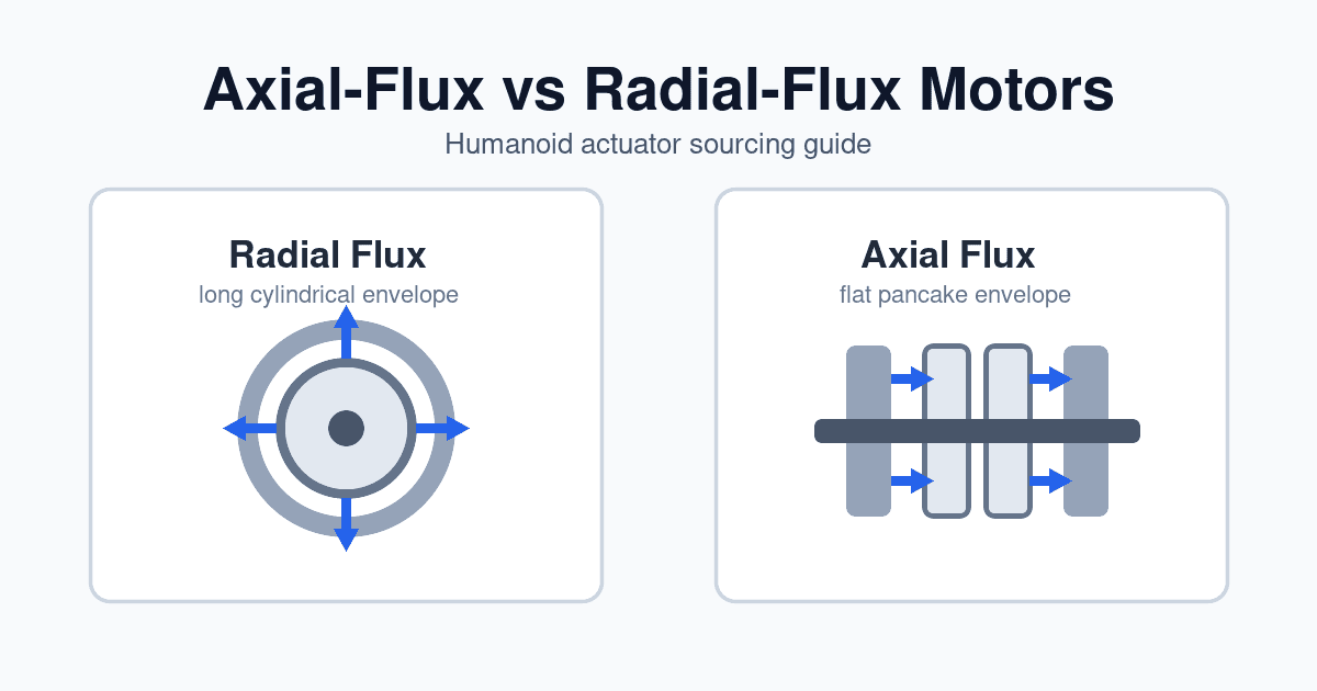
Axial-Flux vs. Radial-Flux Motors for Humanoid Actuators: A 2026 Sourcing Guide
Compare axial-flux vs radial-flux motors for humanoid actuators in 2026: torque density, thermal limits, tooling cost, joint fit, and RFQ sourcing checks.

Engineering NotesProcurement Guides
Crossed Roller Bearings vs. Four-Point Contact Thin-Section Bearings in Humanoid Robot Actuators: Sourcing Moment Rigidity, Preload Classes, and Runout Tolerances
Compare crossed roller and four-point thin-section bearings for humanoid actuators. Review moment stiffness, preload, runout, and RFQ qualification checklist.