
Turn article assumptions into a first actuator family, model class, and evidence request.
Open catalog RFQ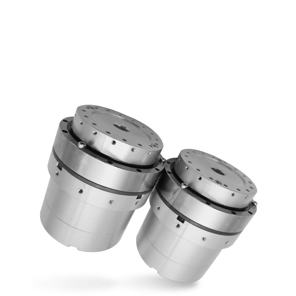
2026/11/08
Power-Off Holding Brakes in Humanoid Actuators: Permanent-Magnet vs. Spring-Applied Sourcing, PWM Economizers, and Thermal Limits
Compare power-off holding brakes for humanoid actuators: PM vs spring-applied designs, PWM heat, torque sizing, and thermal limits. Use the RFQ checklist.
Quick answer: For humanoid robot actuators, power-off holding brakes can retain a gravity-loaded joint after coil power is removed. Compare permanent-magnet (PM) brakes for compact packaging and backlash-free armature designs with spring-applied brakes for mechanical clamping and models explicitly rated for emergency stopping. Neither topology alone establishes personnel protection or prevents a biped from tipping. Choose using guaranteed holding torque at operating temperature, allowable stopping energy, engagement delay, and the complete mechanical load path.
During motion, a power-off brake is released, which normally requires coil excitation. That heat belongs in the actuator thermal budget. A two-stage PWM economizer can reduce release-maintenance power on compatible brakes, but the pulse duration, current window, and savings are model-specific. A reduced-current scheme suitable for a spring-applied brake must not be copied to a PM brake without manufacturer approval.
Use the Humanoid Robot Actuator Catalog to start a shortlist, then send suppliers the RFQ checklist below with your load cases and temperature envelope.
Sourcing Scope, Method, and Verification Limits
Editorial review date: November 8, 2026.
Audience and region: Global mechatronics engineers, humanoid hardware architects, actuators procurement managers, and systems integrators sourcing brushless DC (BLDC) and permanent magnet synchronous motor (PMSM) rotary joints.
Scope: Electromechanical power-off holding brakes integrated into robotic rotary actuators with strain wave, cycloidal, or planetary reducers. Dynamic regenerative motor braking and mechanical locking pins are addressed as boundary comparisons.
Method: Source-based comparison of Kendrion's brake product data, Mayr ROBA servostop Classic, and Miki Pulley BXR-LE brake/controller specifications, with reproducible screening calculations. This article reports no original hardware tests or customer outcomes. The numerical examples are hypothetical; the linked catalog image and diagrams are illustrations. Manufacturer ratings apply to the specified model and conditions, not every brake using the same topology. Applicable safety standards and required performance levels depend on the machine, intended use, market, and risk assessment; this guide does not establish compliance.
Procurement Decision Matrix: Power-Off Brake Architectures
Use this decision matrix during early joint RFQ scoping to align mechanical, electrical, and safety requirements before freezing actuator envelope dimensions.
| Joint Condition or Engineering Requirement | Recommended Brake Topology | Key Trade-off / Implementation Boundary | Relevant Sourcing Pathway |
|---|---|---|---|
| High torque density in a thin axial envelope | Compare compact PM and slim spring-applied designs | Compare actual torque/envelope drawings; verify hot holding torque and release-current limits | Compact Arm & Wrist Actuators |
| Dynamic stopping after immediate drive-power removal | Brake with an explicit emergency-stop rating | Check dynamic torque, speed, single-stop energy, cumulative work, and cooling interval | High-Torque Leg Actuators |
| Low backlash for precision tool manipulation | Backlash-free armature or preloaded hub design | Brake-shaft play, gearbox backlash, and structural compliance are separate specifications | Highly Integrated Rotary Modules |
| Hollow-shaft wiring passage for limb harness (>15 mm bore) | Large-Bore Hollow Spring or PM Brake | Outer diameter increases; friction diameter shifts outward, requiring custom mounting | Hollow-Shaft Joint Actuators |
| Thermal mitigation in sealed, unventilated limbs | Manufacturer-approved brake/economizer pair | Validate pull-in duration, release-maintenance current, ripple, and hot/brownout operation | Actuator Controller & Encoder Kits |
| Backdrivable leg axis with rapid fall recovery | Dynamic Back-EMF Shunt + Low-Ratio Gearbox | Dynamic braking provides no static holding at zero velocity; robot will slowly settle | Force-Control Actuator Selection |
| High-mass bipedal torso or knee pitch holding (100+ Nm output) | Evaluate motor-side and output-side brakes | Motor-side torque benefits from gear ratio but retention depends on transmission integrity | Bipedal Leg Joint Actuators |
| Rapid prototyping & laboratory bench testing | Accessible brake connections and a documented release procedure | Support gravity loads before manual release; use a restrained test fixture | Robotics Lab Sample Kits |
1. The Gravity-Holding Dilemma in Humanoid Robotics
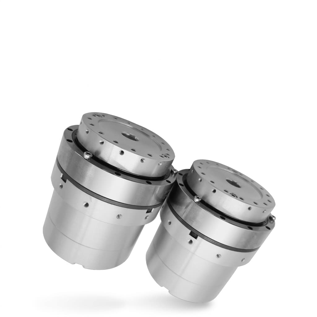
Catalog illustration of a harmonic-drive integrated servo actuator with a brake. The image does not verify internal brake topology, encoder configuration, or a particular safety rating; request a sectional drawing for the quoted model.
Humanoid robots differ fundamentally from wheeled automated guided vehicles (AGVs) or stationary industrial arms: they balance dynamically in a gravity field. A 65 kg humanoid operating in an industrial workstation carries significant potential energy. When power is interrupted—whether by an emergency stop, main battery disconnection, communication bus failure, or overcurrent protection trip—gravity acts instantly on every joint.
1.1 Uncontrolled Collapse vs. Controlled Descent
Without mechanical holding mechanisms, humanoid joints behave according to their mechanical transmission ratio N:
- Quasi-Direct Drive (QDD) Joints: Low ratios often permit backdriving, so gravity can accelerate an unsupported limb after motor torque disappears. Collapse timing depends on posture, inertia, contact conditions, and the control sequence; a universal time-to-fall is not a useful procurement rating.
- High-Ratio Reducer Joints: Gear friction may resist motion, but gear ratio alone does not establish self-locking or safe load retention. Motor inertia reflected to the output is
J_motorN^2; limb inertia reflected to the motor isJ_limb/N^2. Keep the reference shaft explicit when calculating energy or deceleration, and check reducer shock limits separately.
1.2 Stop Categories Under Machinery Safety Standards
Keep IEC 60204-1 stop categories separate from ISO 13849-1 control-system architecture categories and performance levels. A reference to “Category 0” describes a stopping sequence, not a brake's functional-safety certification:
- Stop Category 0: Immediate removal of power to machine actuators produces an uncontrolled stop. It does not imply instant mechanical brake engagement or guaranteed standstill.
- Stop Category 1: A controlled stop retains power long enough to stop, then removes it. For a gravity-loaded joint, a validated sequence may transfer the load to a brake before removing motor torque.
- Stop Category 2: A controlled stop leaves power available. This description alone does not establish a certified Safe Operational Stop function or emergency-stop suitability.
The applicable robot-safety framework, including whether ISO 10218-1 covers the intended application, needs a machine-level assessment. Specify total stopping time, permitted joint displacement, load retention, diagnostics, and behavior after loss of supply. Even locked joints cannot maintain whole-body balance in every pose; support geometry and fall containment remain system requirements.
2. Permanent-Magnet (PM) vs. Spring-Applied Brakes: Operating Physics & Trade-offs
Electromechanical power-off brakes operate on two distinct physical principles: Permanent-Magnet (PM) clamping and Mechanical Spring clamping. Sourcing engineers must understand the mechanical and electromagnetic differences that dictate their performance inside an actuator housing.
2.1 Permanent-Magnet (PM) Brakes: Packaging and Backlash
In a permanent-magnet brake, permanent magnetic flux supplies the attraction needed to clamp an armature to a friction surface without coil power:
- Holding mechanism: The magnetic field provides the clamping force. A leaf-spring armature connection can eliminate coupling play at the brake shaft, but does not eliminate elastic deflection or gearbox backlash.
- Release mechanism: Coil excitation opposes the permanent magnetic field sufficiently for a return spring to separate the friction faces. The correct air gap and excitation range are essential to reliable release.
Sourcing & Engineering Advantages:
- Packaging: Compare torque, diameter, length, and rotor inertia for actual candidate parts rather than assuming PM always has the smallest envelope.
- Released clearance: Correct separation reduces frictional drag; runout, mounting tolerances, and thermal expansion still require checking.
- Published model evidence: Kendrion lists the Slim PM Line SP 61105P00-0001 at 2.7 Nm static torque, 24 V, 12 W, and 0° backlash, with a listed temperature range reaching 120°C. These are model-specific catalog properties, not a hot-torque guarantee for an arbitrary PM brake. See the Kendrion product table.
Engineering Risks & Constraints:
- Thermal limits: Magnet grade, magnetic circuit, friction pair, and coil temperature affect performance. There is no universal 80°C derating threshold or 130°C demagnetization limit for PM brakes. Curie temperature is not the allowable brake operating temperature. Request minimum hot holding torque and the specified measurement location.
- Release window: Excessive as well as insufficient excitation can prevent clean release in a magnetic-cancellation design. Request the manufacturer's current/voltage limits across temperature and air gap; do not assume a generic overvoltage pulse or economizer setting is suitable.
2.2 Spring-Applied Brakes: Mechanical Clamping and Dynamic Ratings
Spring-applied brakes, including Miki Pulley BXR-LE and Mayr ROBA servostop Classic, use mechanical springs to clamp friction surfaces:
- Holding Mechanism: Multiple miniature helical springs or wave springs continuously push an armature plate against an organic or metallic friction disc keyed to the motor shaft.
- Release Mechanism: Applying DC power to the electromagnetic coil pulls the armature plate against the springs toward the coil housing, opening the air gap and freeing the friction disc.
Sourcing & Engineering Advantages:
- Power-off clamping: Spring force remains available without electrical supply. Wear, contamination, spring damage, and incorrect assembly can still defeat load retention.
- Emergency-stop options: Mayr identifies ROBA servostop Classic as spring-applied and suitable for emergency braking, with high permitted friction work. The page also lists use up to 120°C; obtain the configuration-specific limits and operating instructions before approving a joint. See Mayr's product documentation.
- Economizer options: Some spring-applied designs need less current after the armature has seated. The approved brake/controller combination determines how far current may be reduced.
Engineering Risks & Constraints:
- Hub backlash: Sliding hub connections can introduce play; other designs reduce it. Ask for measured brake-shaft backlash and stiffness. With an ideal reducer, motor-side angular play is divided by gear ratio at the output, where gearbox play and compliance must also be added.
- Temperature and envelope: Spring-applied does not mean heat-proof. Coil insulation, friction material, spring characteristics, and mounting tolerances still impose limits. Slim designs exist, so compare drawings instead of imposing a topology-wide thickness range.
3. Thermal Dissipation in Sealed Limbs & PWM Economizer Circuits
Include release-coil power dissipation in the thermal budget. “Holding current” in an economizer specification often means current maintaining the released state, not current holding the limb against gravity.
Illustrative Release-Coil Heat Budget:
12 Actuators × 12 Watts per Coil = 144 Watts of Parasitic Heat!
Trapped inside IP54/IP65 aluminum limb housings next to motor windings & encoders.
In a compatible spring-applied brake, the coil first pulls the armature against the springs. Once seated, the smaller magnetic gap can allow reduced release-maintenance current. This explanation does not apply unchanged to PM field cancellation. As a concrete example, the Miki Pulley BXR-LE controller table specifies a 24 V pulse lasting 0.2 seconds, followed by 7 V constant excitation using PWM. Its supply, ambient-temperature, and output-current limits also matter; those settings are not instructions for other brakes.
3.1 Mathematical Derivation of Economizer Power Reduction
For steady DC excitation, coil copper heating is:
P = V^2 / R = I^2 × RFor a hypothetical constant-resistance coil, assume R = 40 Ω and a 24 V supply. This is a teaching example, not a BXR-LE model specification:
-
Full-Voltage Continuous Operation (
24 V):P_nominal = 24^2 / 40 = 14.4 WIn a 14-actuator humanoid (4 hip, 2 knee, 4 ankle, 4 shoulder), running all brakes continuously at nominal voltage burns:
P_total = 14 × 14.4 = 201.6 WTemperature rise cannot be obtained from watts alone: it depends on thermal resistance, mounting, airflow, neighboring motor heat, and duty cycle.
-
Two-Stage PWM Economizer Operation (
7 VHolding): Suppose the manufacturer has approved the illustrated 80 ms release pulse and a current-regulated maintenance level of0.175 A. At40 Ω, that current corresponds to7.0 VDC:P_holding = 7.0^2 / 40 = 1.225 WPower reduction percentage:
Power reduction = (14.4 - 1.225) / 14.4 × 100% = 91.5%The illustrative steady-state total becomes 17.15 W rather than 201.6 W, a 91.5% reduction in coil heating. This excludes pull-in energy and driver losses.
For PWM, use measured RMS coil current: P_copper=I_rms^2R. Substituting average voltage into V^2/R is only an approximation when current ripple is small and a suitable recirculation path maintains current. Without that condition, 29.2% voltage duty does not establish 91.5% heat reduction. Copper resistance also rises with temperature; verify hot release current, cold overcurrent, minimum supply, switching ripple, and thermal soak with the selected driver.
3.2 Inductive De-Energization & Engagement Delay (t_engage)
When an E-stop occurs, the brake coil must de-energize to let the mechanical springs or permanent magnets clamp the armature plate. Because the brake coil is a large inductor (L), the current cannot drop instantaneously:
τ = L / R_circuitWith a simple flyback diode, circulating current can delay engagement. The L/R expression describes an approximate current-decay timescale, not total braking response: suppression voltage, dropout current, armature travel, and torque buildup also matter. Measure command-to-torque timing with the actual harness and driver.
Ask the supplier to document:
- Suppression method: A correctly rated TVS/Zener or active clamp can accelerate current decay, but its voltage and pulse-energy rating must suit the coil, driver, insulation, and EMC requirements.
- Power-loss behavior: Identify the current-decay path after loss of control power, any residual supply, output faults, and whether brake feedback confirms the mechanical state. Two switching devices alone do not establish a validated safety architecture.
When reviewing Actuator Controller & Encoder Kits, request the brake-output schematic, approved economizer settings, and measured switching traces for your proposed combination.
4. Motor-Side vs. Link-Side Brake Placement
Actuator architects face a fundamental placement choice: mount the brake on the high-speed motor shaft (before the gearbox) or on the low-speed link output flange (after the gearbox).
Mechanical Placement Dilemma:
Motor-Side: Small, lightweight brake, but relies on transmission load path.
Link-Side: Holds closer to the load; needs full output torque and a verified mounting path.| Evaluation Parameter | Motor-Side Brake Placement | Link-Side (Output Flange) Brake Placement | Sourcing Implications & Best Practices |
|---|---|---|---|
| Required Holding Torque | Ideal screening: T_brake ≥ K_marginT_joint/N, without crediting gear friction | Screening: T_brake ≥ K_marginT_joint | Use guaranteed minimum torque at temperature and wear limit; static gear friction is not a known efficiency. |
| Brake Mass & Envelope | Often smaller because required shaft torque is lower | Often larger because full output torque is required | Compare actual bore, friction radius, mounting, and mass; no universal mass multiplier applies. |
| Rotary Inertia Added to Motor | Adds rotor inertia directly to the motor shaft | Adds output inertia, reflected to the motor by division by N^2 | Include rotor, brake, reducer, and reflected limb inertia in the acceleration model. |
| Failure Containment Scope | Does not protect against downstream gear, shaft, or coupling failure | Can retain the load after an upstream failure if its own load path remains intact | Check flange, shaft, fasteners, housing, and bearing support for both placements. |
| Backlash Impact at Limb | Gearbox backlash and windup remain present at the joint output | Can bypass gearbox play, but brake and structure still deform | Specify permitted output displacement under load rather than assuming perfectly rigid retention. |
| Dynamic E-Stop Shock on Gears | Brake clamping shock passes through gear teeth to stop limb | Friction shock absorbed directly at joint structure; bypasses gearhead | Motor-side dynamic stopping requires checking gearhead momentary peak shock torque (T_shock). |
4.1 Gearbox Shock During Motor-Side Dynamic Stopping
When a motor-side brake clamps dynamically while a joint is rotating at output velocity ω_joint, the gearhead is subjected to severe shock torque. The decelerating torque transmitted across the gear teeth is:
T_gear_shock = J_limb × α_stop + T_gravityWhere α_stop is the deceleration angular acceleration determined by the brake torque and reflected inertia:
α_motor = (T_brake_dynamic - T_load_reflected) / (J_motor + J_brake + J_limb / N^2)These are idealized rigid-body magnitudes for motion in which gravity opposes braking; α_stop=α_motor/N. Require positive net decelerating torque. A real peak-load assessment also needs reducer inertia, compliance, torque-rise time, impact loads, and drive behavior. Compare measured stop traces with the gearhead's momentary torque limit; a static holding rating cannot establish that the transmission survives dynamic engagement.
5. Joint-by-Joint Brake Allocation Framework
Brake allocation trades mass, thermal load, cost, and consequences of uncontrolled motion. Treat the following as a shortlist framework; the machine risk assessment determines which joints need retention, controlled descent, redundancy, or external support.
Humanoid Actuator Brake Sizing by Limb Zone:
Torso & Leg Axes: Evaluate load retention, balance loss, and fall containment together.
Shoulder & Elbow: Evaluate payload drop and accessible pinch/crush hazards.
Wrist & Neck: Check tool mass and contact hazards before considering brake omission.
5.1 Leg & Pelvis Joints (Hip Pitch, Knee, Ankle Pitch)
- Gravity risk: Frequently high; posture and support conditions determine collapse behavior.
- Candidate topology: Compare motor-side spring-applied and PM designs, or output-side retention where transmission failure must be contained.
- Key sourcing check: Establish the required torque margin and minimum hot/worn holding torque, then validate displacement during power loss. The example factor of 1.8 below is an assumption, not a prescribed safety factor.
5.2 Upper Arm & Shoulder Joints (Shoulder Pitch/Roll, Elbow)
- Gravity Risk: High to Moderate. Uncontrolled drops can crush human hands, damage machine tools, or shatter end-effector gripper fingers.
- Candidate topology: Compare compact PM and spring-applied designs using payload retention, envelope, and backlash requirements.
- Key sourcing check: Include added rotor inertia in servo sizing; no universal brake-to-motor inertia ratio guarantees bandwidth.
5.3 Wrist, Neck, and Dexterous Finger Joints
- Gravity risk: Application-dependent. A heavy tool, sharp end effector, or accessible neck joint can remain hazardous despite a small actuator.
- Candidate topology: Brake omission or dynamic damping requires an accepted loss-of-power behavior; neither motor phase shorting nor reducer friction establishes static retention.
- Key sourcing check: Document the maximum tool load, permitted descent, and inverter fault behavior before accepting the mass saving.
6. Mathematical Sizing Walkthrough: Sizing a Humanoid Knee Actuator Brake
Use this hypothetical example to challenge supplier quotations. It illustrates torque and energy screening, not approval of a real humanoid knee.
Sizing Scenario: Bipedal Humanoid Knee Joint Pitch Axis
- Total Robot Mass (
M):65 kg - Static Gravitational Load on Single Knee (
m_knee):45 kg(posture: squatting stance, center of mass shifted forward) - Effective Lever Arm (
r_com):0.22 m - Gearhead Ratio (
N):80:1(precision strain wave gearhead) - Gear friction assumption: No holding credit; use the ideal torque ratio for initial screening.
- Illustrative Margin (
K_margin):1.8 ×, pending load-case and risk review.
Step 1: Calculate Static Gravitational Joint Torque
T_joint_gravity = m_knee × g × r_com = 45 × 9.81 × 0.22 = 97.12 N·mStep 2: Calculate Torque Reflected to the Motor-Side High-Speed Shaft
Without crediting uncertain gear friction, divide joint torque by ratio. A running backdrive-efficiency number does not establish static friction at standstill:
T_motor_reflected = T_joint_gravity / N = 97.12 / 80 = 1.214 N·mStep 3: Apply Sizing Safety Factor (K_margin)
Apply the assumed margin, then compare against minimum guaranteed holding torque at the specified temperature, wear condition, and mounting orientation:
T_brake_required ≥ K_margin × T_motor_reflected = 1.8 × 1.214 ≈ 2.19 N·mSourcing output: For these assumptions, request at least 2.19 Nm minimum holding torque under the specified service conditions. A room-temperature nominal rating of 2.5 Nm does not by itself prove this requirement. Dynamic torque and allowable stop energy require separate checks.
Step 4: Kinetic Energy Dissipated During Emergency Stop
Assume an emergency stop occurs while the knee joint is swinging forward at ω_joint = 4.0 rad/s (≈ 230^°/s):
- Motor Speed:
ω_motor = ω_joint · N = 4.0 × 80 = 320 rad/s(≈ 3,055 rpm) - Combined Rotor + Brake Inertia (
J_motor+brake):3.5 × 10^-5 kg·m^2 - Point-mass limb approximation:
J_limb=45 × 0.22^2=2.178 kg·m^2, assuming the same radius for the simplified torque and inertia model. - Reflected Limb Inertia (
J_limb_refl = J_limb / N^2):3.4031 × 10^-4 kg·m^2 - Total High-Speed Inertia (
J_total):3.7531 × 10^-4 kg·m^2, excluding reducer inertia for this example.
Initial kinetic energy to account for in the stop:
E_k = 0.5 × J_total × ω_motor^2 = 0.5 × 3.7531 × 10^-4 × 320^2 ≈ 19.22 JSourcing check: Kinetic energy alone is insufficient for a descending axis. In a simplified stop where the brake absorbs all motion energy, include released gravitational potential energy: W_brake=E_k+∫ T_gravity(θ) dθ. At approximately constant 97.12 Nm over a further 0.1 rad descent, gravity adds about 9.71 J, giving 28.93 J before omitted inertia, delay effects, and design allowances. The descent angle is an assumption, not a predicted stop distance. Request a dynamic model and test evidence covering initial speed, delay, dynamic torque, single-event work, cumulative work, repetition interval, and temperature. A joule rating alone cannot guarantee repeated-stop life.
7. 10-Point RFQ Procurement Checklist for Humanoid Actuator Brakes
Before signing sample purchase orders or locking production BOMs, issue this 10-point technical checklist to potential actuator and brake vendors:
- Holding Torque Test Temperature: Is the specified static holding torque measured at room ambient (20°C) or at the actuator's maximum rated continuous thermal limit (80°C–100°C)? Request a thermal derating curve.
- Brake Topology Specification: Does the quotation specify a Permanent-Magnet (PM) or Spring-Applied brake? If PM, what is the magnet grade (e.g., N38SH or Sm2Co17 for high-temperature stability)?
- Backlash & Armature Attachment: What is the mechanical backlash at the brake shaft? Does the armature use a zero-backlash leaf spring or a sliding splined hub?
- Permissible Dynamic Friction Work (
W_max): What is the maximum allowable single-event dynamic stopping energy (in Joules), and what is the maximum cumulative friction work before lining replacement? - Two-Stage Drive & Economizer Compatibility: What are the approved pull-in voltage/current, pulse duration, and continuous release-maintenance current? Request the PM release window where applicable, plus allowed ripple and brownout behavior.
- Engagement Timing & Internal Snubbers: What is the brake engagement delay (
t_engage) and release delay (t_release)? Does the vendor require external Zener clamping, or is a fast-demagnetization flyback circuit integrated into the servo driver? - Coil Insulation Class & Dielectric Rating: What are the insulation class, winding-temperature limit, and specified dielectric withstand test? Class F (155°C) or Class H (180°C) does not by itself establish allowable ambient temperature, friction performance, or actuator operating temperature.
- Hollow-Shaft Inner Diameter Clearance: Does the brake rotor and stator assembly maintain the necessary center bore clearance to accommodate internal motor phase leads, dual-encoder BiSS-C wiring, and DC power harnesses?
- Manual Release Procedure: Is a mechanical release or external test connection provided, and what fixture supports the gravity load before release? Request isolation, load-support, and re-engagement instructions; do not assume an exposed 24 V header is an approved override.
- Factory Run-In & Burnishing Status: Are brake friction surfaces pre-burnished at the factory before final inspection, or does the buyer have to execute a field-burnishing procedure to reach 100% nominal holding torque?
8. Frequently Asked Questions (FAQ)
Q1: Can we replace mechanical brakes entirely by shorting the motor phase windings (dynamic back-EMF braking)?
No, when static gravity holding is required. Phase shorting can provide speed-dependent damping, subject to motor resistance, inductance, current limits, and inverter state. In a simplified low-speed model, braking torque is approximately proportional to speed and approaches zero at standstill. It cannot be counted as static load retention. Verify whether the intended shorting state remains available after loss of control power.
Q2: What happens if a permanent-magnet brake is driven with too high a release voltage?
A magnetic-cancellation brake has an approved excitation window. Too much or too little coil current can prevent full release and create drag or unintended re-engagement. The limits depend on the specific magnetic circuit, air gap, coil temperature, and driver. Request the manufacturer's release-current envelope rather than assuming a universal percentage overvoltage threshold.
Q3: Why can a joint slip during an E-stop despite a static torque margin?
Possible causes include engagement delay, dynamic torque below the static rating, hot friction surfaces, contamination, overload, or a failed downstream load path. During delay, gravity can add speed and stopping energy. Measure command-to-torque time and load displacement, then compare dynamic torque and friction work against the approved operating envelope. A faster clamp may reduce delay, but cannot by itself fix an undersized brake or establish a safe stop.
Q4: How much mass does a power-off holding brake add?
Use the quoted brake, hub, mounting, wiring, and driver masses. As a model-specific reference, Miki Pulley's BXR-LE table lists 0.40 kg for the 3.20 Nm BXR-050-10LE brake. That figure does not predict the mass of a complete joint or another topology. Multiply the actual installed mass by the selected joint count and include its location in the robot inertia model.
Q5: Can a holding brake be installed on the output side of a strain wave gearhead?
Yes, if packaging and structural design permit it. An output brake must react full joint torque, whereas a motor-side brake benefits from the ratio. Direct output retention can address upstream transmission failure, but only if the output shaft, brake mounting, housing, and fasteners provide an intact load path. Compare actual designs rather than assuming output-side installation is always impractical.
Q6: Can brake switching interfere with absolute encoders?
Yes. Inductive switching produces voltage transients (V=L dI/dt), and PWM creates repeated switching edges. Check suppression, grounding, cable routing, shielding, and physical separation between brake power and encoder signals. Verify encoder integrity during repeated release/engagement and power-loss tests in the assembled actuator; a wiring recommendation alone is not EMC evidence.
Q7: What power consumption should we expect from a PWM economizer?
For the hypothetical 40-ohm coil above, 24 V DC dissipates 14.4 W; a low-ripple 0.175 A maintenance current dissipates 1.225 W. This is 91.5% lower steady coil heat, excluding pull-in pulses and driver losses. Actual power depends on the brake, temperature, ripple, and release duty cycle. Request measured input power and coil RMS current for the approved brake/controller pair.
Q8: How many emergency dynamic stops can a holding brake endure?
There is no topology-wide cycle count. Suppliers specify speed, energy per stop, cumulative work, temperature, and intervals between events. For example, Kendrion's listed SP 61105P00-0001 PM configuration includes 500 emergency stops with model-specific work and speed limits. That listing cannot be transferred to another PM brake or used as a maintenance interval without the operating conditions and inspection instructions.
Q9: Can an actuator holding brake provide active torque control or damping?
Treat an ordinary power-off holding brake as an engage/release device unless the manufacturer expressly rates it for controlled slipping. Repeated slip dissipates heat and wears the friction pair. Use the servo control or a purpose-designed damping device for continuous torque modulation, and keep load-retention requirements separate.
Q10: How do hollow-shaft joint designs accommodate power-off brakes?
An annular brake can preserve a central wiring passage. Verify usable bore after the hub, fasteners, and connectors are installed; also check cable bend radius, insulation clearance, and strain relief. Include these dimensions in the RFQ for Hollow-Shaft Joint Actuators, rather than assuming a catalog bore guarantees an installable harness.
9. Sources and References
Manufacturer pages checked on November 8, 2026. These sources support the identified product examples; they do not certify a robot or substantiate universal limits for an entire brake topology.
- Mayr — ROBA servostop Classic: Spring-applied operating principle, emergency-braking suitability, temperature specification, configuration data, and links to operating instructions. Confirm the final variant's friction-work limits.
- Kendrion — Brake product finder: Separate static/dynamic torque definitions and per-model fields for backlash, temperature, PWM compatibility, single-stop work, and emergency-stop count. The named Slim PM model is an example, not a recommendation for the worked knee scenario.
- Miki Pulley India — BXR-LE model: Spring-actuated brake specifications and BEM-24ESN7-120N controller data, including the 0.2-second 24 V pulse followed by 7 V maintenance excitation. Use the complete brake/controller operating limits.
Stop-category terminology is contextual guidance, not a clause-by-clause standards interpretation. The machine integrator must confirm applicable editions and requirements independently.
10. Next Steps: Streamline Your Actuator Sourcing
For a useful supplier review, send the worst-case gravity torque and posture, gear ratio, motor speed at power loss, inertia model, required bore, temperature range, permitted displacement, and expected emergency-stop frequency. Ask the vendor to return minimum hot/worn holding torque, dynamic work limits, a brake/controller drawing, and a proposed fixture-test plan.
- Leg-axis shortlist: Review High-Torque Leg Actuator Modules and request the exact brake option and thermal evidence.
- Upper-limb packaging: Compare Compact Arm and Wrist Actuators and Highly Integrated Rotary Modules using the same load and backlash requirements.
- OEM handoff: Share your RFQ packet through Actuator BOM Integration. Confirm compatibility and validation responsibilities before freezing the production BOM.
Author

Categories
Buyer path
After Reading
Use the guide to choose the next sourcing action.
Convert the guide into application-risk notes before asking for samples or controlled files.
Send prototype contextCarry accepted article checklists into sample release, pilot supply, and OEM documentation control.
Prepare OEM sample planSourcing Scope, Method, and Verification LimitsProcurement Decision Matrix: Power-Off Brake Architectures1. The Gravity-Holding Dilemma in Humanoid Robotics1.1 Uncontrolled Collapse vs. Controlled Descent1.2 Stop Categories Under Machinery Safety Standards2. Permanent-Magnet (PM) vs. Spring-Applied Brakes: Operating Physics & Trade-offs2.1 Permanent-Magnet (PM) Brakes: Packaging and BacklashSourcing & Engineering Advantages:Engineering Risks & Constraints:2.2 Spring-Applied Brakes: Mechanical Clamping and Dynamic RatingsSourcing & Engineering Advantages:Engineering Risks & Constraints:3. Thermal Dissipation in Sealed Limbs & PWM Economizer Circuits3.1 Mathematical Derivation of Economizer Power Reduction3.2 Inductive De-Energization & Engagement Delay (
t_engage)4. Motor-Side vs. Link-Side Brake Placement4.1 Gearbox Shock During Motor-Side Dynamic Stopping5. Joint-by-Joint Brake Allocation Framework5.1 Leg & Pelvis Joints (Hip Pitch, Knee, Ankle Pitch)5.2 Upper Arm & Shoulder Joints (Shoulder Pitch/Roll, Elbow)5.3 Wrist, Neck, and Dexterous Finger Joints6. Mathematical Sizing Walkthrough: Sizing a Humanoid Knee Actuator BrakeSizing Scenario: Bipedal Humanoid Knee Joint Pitch AxisStep 1: Calculate Static Gravitational Joint TorqueStep 2: Calculate Torque Reflected to the Motor-Side High-Speed ShaftStep 3: Apply Sizing Safety Factor (K_margin)Step 4: Kinetic Energy Dissipated During Emergency Stop7. 10-Point RFQ Procurement Checklist for Humanoid Actuator Brakes8. Frequently Asked Questions (FAQ)Q1: Can we replace mechanical brakes entirely by shorting the motor phase windings (dynamic back-EMF braking)?Q2: What happens if a permanent-magnet brake is driven with too high a release voltage?Q3: Why can a joint slip during an E-stop despite a static torque margin?Q4: How much mass does a power-off holding brake add?Q5: Can a holding brake be installed on the output side of a strain wave gearhead?Q6: Can brake switching interfere with absolute encoders?Q7: What power consumption should we expect from a PWM economizer?Q8: How many emergency dynamic stops can a holding brake endure?Q9: Can an actuator holding brake provide active torque control or damping?Q10: How do hollow-shaft joint designs accommodate power-off brakes?9. Sources and References10. Next Steps: Streamline Your Actuator SourcingMore Posts
Engineering NotesProduct Engineering
Humanoid Actuator Thermal Management: Sourcing for Continuous Torque
A 2026 procurement guide to thermal derating in humanoid robot actuators. Learn how to evaluate cooling architectures and source for continuous, rather than just peak, torque.

Engineering NotesProcurement Guides
Quasi-Direct Drive (QDD) vs. High-Ratio Geared Actuators for Humanoids: Sourcing & Sizing Guide
Compare QDD vs high-ratio humanoid actuators by inertia, backdrivability and thermal duty. Use the sizing example and RFQ checklist to shortlist joint modules.
Engineering NotesProcurement Guides
Crossed Roller Bearings vs. Four-Point Contact Thin-Section Bearings in Humanoid Robot Actuators: Sourcing Moment Rigidity, Preload Classes, and Runout Tolerances
Compare crossed roller and four-point thin-section bearings for humanoid actuators. Review moment stiffness, preload, runout, and RFQ qualification checklist.